How to Possition Motor in Airsoft Gun
How to Possition Motor in Airsoft Gun
Connect ESCs and Motors
This article explains how to connect the ESCs, motors and propellers to a autopilot. The Pixhawk is used as an example but other autopilots are connected in a similar way.
Connect the power (+), ground (-), and point (s) wires for each ESC to the autopilot's chief output pins past motor number. Find your frame type beneath to make up one's mind the assigned order of the motors.
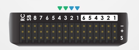
Pixhawk Outputpins (numbered). First 4 pins are colour-coded for connecting a Quadframe
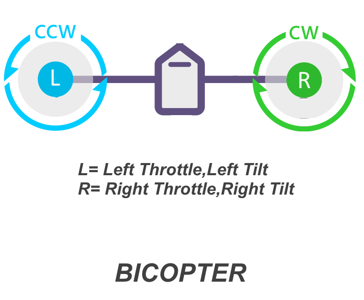
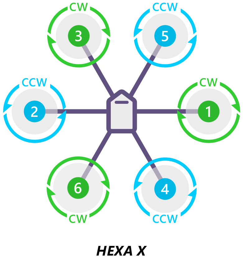
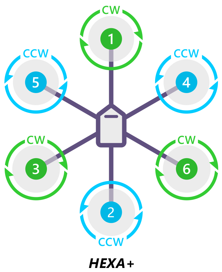
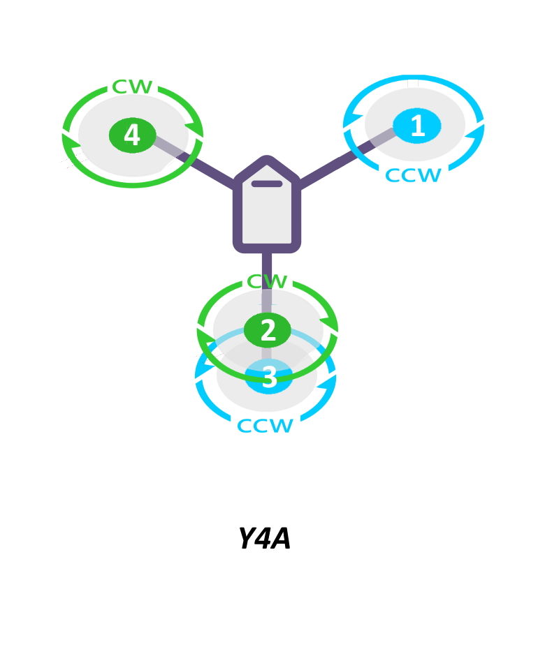
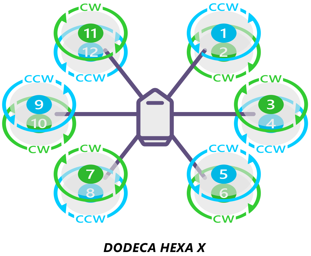
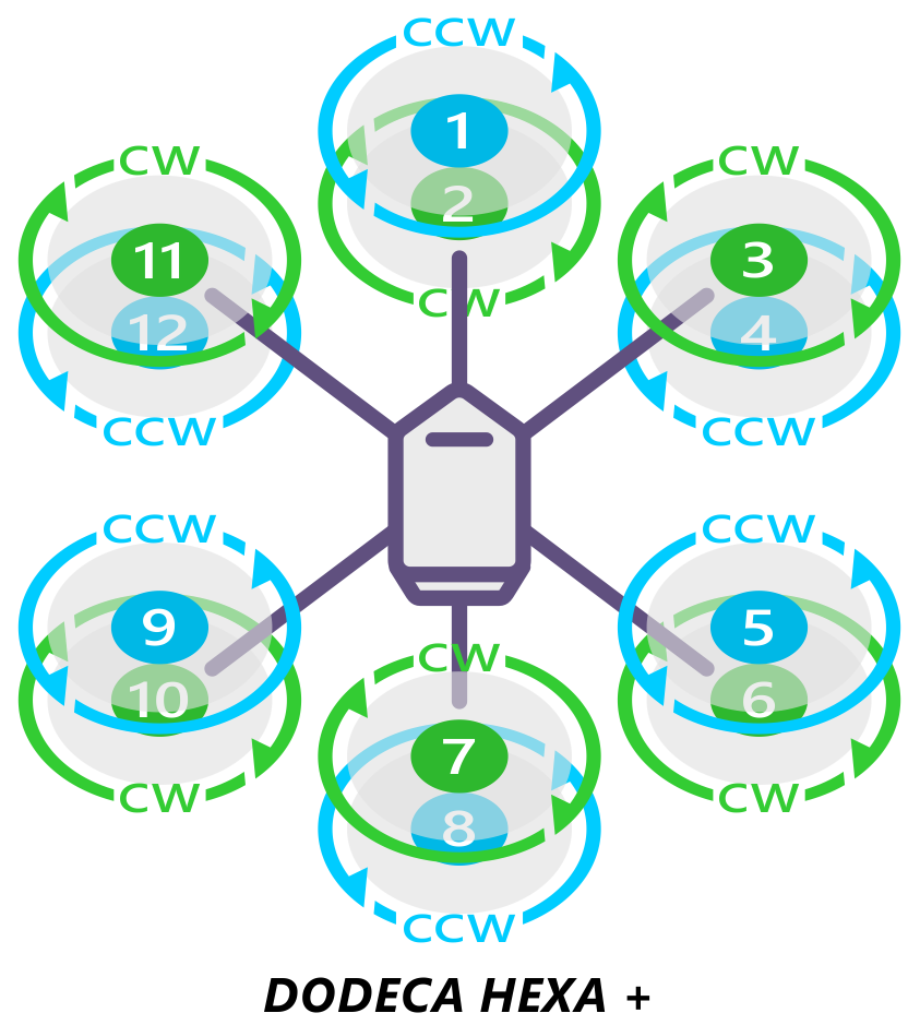
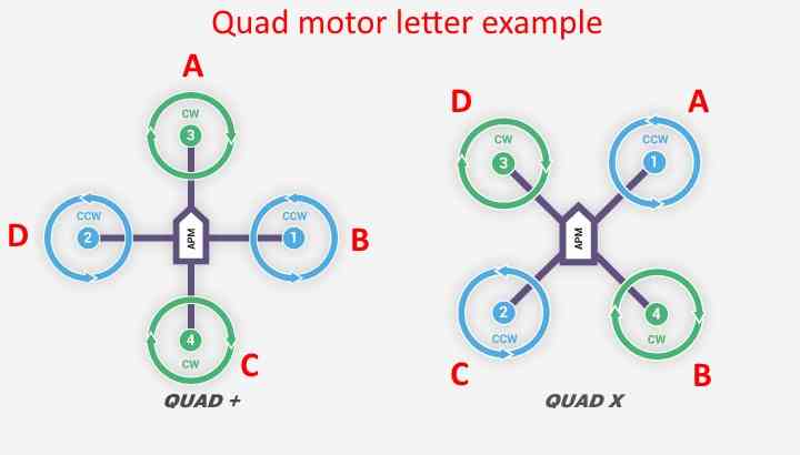
Motor social club diagrams
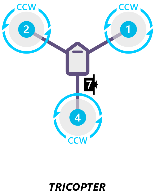
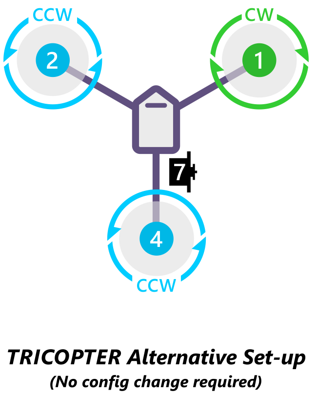
The diagrams beneath bear witness motor order for each frame blazon. The numbers indicate which output pin from the autopilot shoould be continued to each motor/propeller. The propeller direction is shown in green (clockwise, CW) or blue (counter-clockwise, CCW)
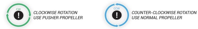
Fable for motor-order diagrams
Tricopter
Note
If the direction of your tail servo is going the incorrect way in response to yaw so either the RCn_REVERSE RC input direction or the tilt servo'south SERVOn_REVERSE parameter should be set to ane (from 0), See TriCopter setup page for details.)
Bicopter
Hexacopter
Y4
DodecaHexacopter
Recognizing clockwise and counterclockwise propellers
The diagrams above bear witness ii types of propellers: clockwise (called pushers) and counterclockwise (chosen pullers). The near reliable to recognize the correct propeller type by its shape as shown beneath. The thicker edge is the leading edge which moves in the direction of rotation. The abaft edge is more radical scalloped and usually thinner. 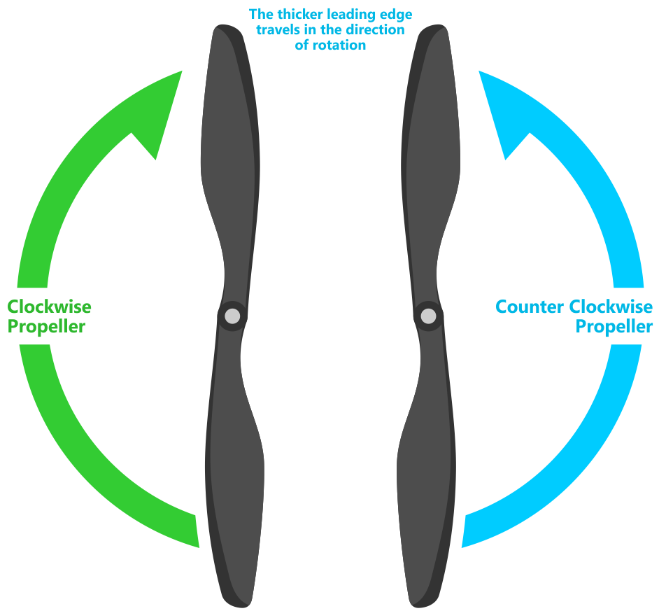
Testing motor spin directions
If you have completed the Radio and ESC calibration, you lot can check that your motors are spinning in the correction direction:
-
Make sure there are no propellers on your copter!
-
Turn transmitter on and ensure the flight mode switch is set to Stabilize.
-
Connect battery.
-
Arm copter by property the throttle down and rudder right for 5 seconds.
-
If it fails to Arm with the throttle downward and to the right and the motors will not spin, information technology has probably failed the Pre-Arm Safety Bank check.
- Pre-Arm safety bank check failure is also indicated by the red arming lite double flashing and and then repeating.
- If the Pre-Arm bank check fails go to the Prearm Rubber Cheque Page and correct the problem or disable the check earlier continuing.
-
When y'all can Arm successfully, apply a small amount of throttle, and find and note spin direction of each motor. They should match directions shown in the images above for the frame you've chosen.
-
Reverse any motor spinning in the incorrect management.
Tip
- Motor Direction is reversed but by interchanging two of the
-
three ESC to motor ability leads.
Checking the motor numbering with the Mission Planner Motor test
An culling way to cheque that the motors have been hooked up correctly is to use the "Motors" test in the Mission Planner Initial Setup carte.
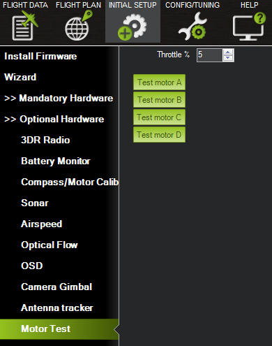
Mission Planner: Motor Examination
When connected to the vehicle via MAVLink, you tin can click on the green buttons shown above and the corresponding motor should spin for five seconds. Letters stand for to motor numbers as shown in the example below.
- Take off your props offset!
- If no motors turn, raise the "Throttle %" to 10% and endeavour over again. If that doesn't work, try fifteen%
The first motor to spin will be the one located straight forrad in the instance of + configuration, or the start motor to the right of straight frontward in the example of 10 configuration. The motor test will so continue in a clockwise rotation.
In the case of X8, it volition spin the summit front-right motor first, then the bottom front end-right, and go along effectually with the aforementioned blueprint.
OctoV will spin the front-correct motor first, and so once again, proceed clock-wise until reaching the front end left motor.
Using a Ability Distribution Lath
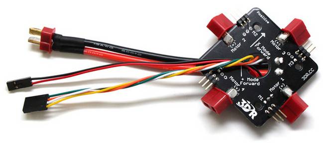
In that location are ii methods of connecting the motor outputs. Either connect the electronic speed controllers (ESCs) directly to the autopilot OR use a power distribution board (PDB).
When using a PDB, connect the power (+), ground (-), and signal (s) wires for each ESC to the PDB according to motor number. Find your frame blazon below to determine the assigned order of the motors. So connect the indicate wires from the PDB to the main output bespeak pins on the autopilot (ensuring that the motor gild numbers lucifer the chief output pin numbers on the controller). If y'all are using a power module, it is optional to connect the power and ground wires from the PDB to the autopilot board. If y'all would like to utilize these cables in addition to or instead of the power module or every bit a common point for low current servos, connect the ground (-) wire to a primary output ground (-) pivot and the power (+) wire to a main output ability (+) pin.
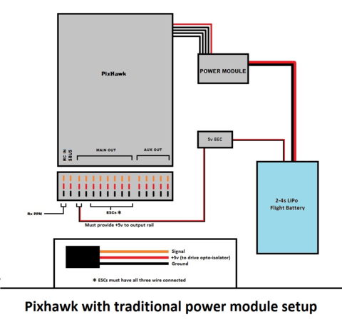
KDE (and other) Opto Isolated ESCs
The KDEXF-UAS and KDEF-UASHV Series are opto-isolated and practice not provide BEC power output for the peripheral equipment. They crave +5V to ability the opto-isolator and while the Pixhawk can be powered from the servo rail, it does not provide +5V to the servo rail. The ESCs must be powered past a BEC or with a jumper from an unused connector on the board. It is strongly recommended that you lot utilize a BEC to power the rail rather than a jumper.
The KDE ESCs have fixed PWM ranges then y'all must manually set the output range of each PWM signal then that RCx_MIN is 1100 and RCx_MAX is 1900us using the Avant-garde Parameter or Full Parameter Settings Page in the planner.
Pixhawk ESC problems
Some ESCs take been reported equally not working with Pixhawk.
The Pixhawk should work with every ESC that works with a normal RC receiver (because it sends the same type of signal) but there is ane known exception, the EMAX ESC.
In most cases problems are due to incorrect wiring. Always connect bespeak and ground. Check your ESC type to decide how to connect the +5V line. For Pixhawk you lot must connect both the signal and the indicate basis in club to make the ESC work.
For more information see this video.
How to Possition Motor in Airsoft Gun
Posted by: johnsonnathothered.blogspot.com
0 Response to "How to Possition Motor in Airsoft Gun"
Post a Comment